AASHTO Guidance FHWA
Table Of Content

A18.) Adding decorative hardware to a breakaway luminaire support might affect proper performance. A5.) Yes, research sponsored by the NCHRP and pooled fund studies at the Midwest Roadside Safety Facility (Lincoln, NE) and the Texas Transportation Institute (College Station, TX.) is underway. Placement next to slope break points, transitions, terminals, etc., will be tested and/or evaluated.
Frequently Asked Questions: Barriers, Terminals, Transitions, Attenuators, and Bridge Railings
This memorandum supersedes the FHWA memorandum dated July 19, 1990 on the RDG adoption. New steel guardrail posts should conform to AASHTO M270 / ASTM A-36 steel and AASHTO M111 / ASTM A-123 for the galvanizing. When delivered to construction sites, these components are typically accompanied by mill certifications. Salvaged material is often an assortment of varying ages, bolt-hole locations, steel grades, etc. State highway agency should be able to track and verify the source of these materials to ensure the barrier will perform as designed because it is difficult to establish that salvaged guardrail material meets proper specifications.

AASHTO Guidance
Federal Way Link Extension Draft EIS Appendix H I-5 Alternative Location - soundtransit.org
Federal Way Link Extension Draft EIS Appendix H I-5 Alternative Location.
Posted: Wed, 20 Sep 2023 19:34:50 GMT [source]
However, the minimum 18 inch horizontal clearance to vertical obstructions must still be met unless a design exception is approved. In an attempt to improve roadway safety and to evaluate systems that are reflective of in service conditions, all future test documentation should include the vertical elements that the manufacturers market with the curbing systems. However, FHWA field offices often raise numerous issues that involve interpretations, extrapolations, device selection, hardware deployment, or simply trying to fit safety devices into real world conditions. The following questions and answers offer clarification on certain roadside issues not covered by FHWA policy or topics that simply need additional explanation.
Clear Zone and Horizontal Clearance
The revisions to Chapter 6 include the updated guidance on the use of the median barrier. Additional changes to the chapter include a new section on High-Tension Cable Barrier Systems and guidance on the placement of cable barriers. A11.) In the early 2000’s the Midwest Roadside Safety Facility (MWRSF) conducted a study to develop a better-performing roadside barrier.
Bridge Railings
That research indicated that the performance of the G4 (1S) strong steel post guardrail improved when the splices were moved to mid-span. Increasing the blockout depth also improved crash test performance, as did raising the height of the rail from 27 3/4” to 31” which reduced the embedment of the post. The MGS has also been crash tested with 8” blockouts and Texas DOT is currently (June 2012) preparing to submit a Request for Eligibility.) Other systems were subsequently developed that also have a 31-inch mounting height. Plans and specifications for projects on the National Highway System (NHS) must provide for facilities, including the roadsides that are conducive to safety. The RDG is included in the FHWA Policy and Guidance Center (PGC) as “guidance” for use when designing highway projects and addressing roadside issues on the NHS. The first edition of the RDG was adopted by the FHWA through the Federal Register, effective July 25, 1990, and recommended as the document States should use to develop roadside safety design policies.
They are the considered opinions of engineers in the FHWA Office of Safety Design and the FHWA Resource Center with helpful input from members of the American Traffic Safety Services Association's Guardrail Committee. A9.) The recommendations for increased w-beam height are based on crash testing and an increase in the number of high center-of-gravity vehicles currently traveling on highways and roads compared to the 1960’s when the 27-inch standard was set. A1.) No, only new posts and rails that are accompanied by a material certification should be allowed on Federal-Aid projects or on NHS routes.
Barrier Terminals and Crash Cushions
A13.) The guardrail should be raised to 29 inches, which represents the target height for new installations of strong post w-beam systems. If the pavement work requires the barrier to be moved, then the posts should be carefully extracted and, if in good condition, re-driven at the new location so that the rail will be at 29 inches. If the barrier does not need to be moved, then raising the blockout up to three inches is a common practice. This will require field drilling or punching of a new hole in the guardrail post.
The Low-Cost Dropoff Solution FHWA - Federal Highway Administration
The Low-Cost Dropoff Solution FHWA.
Posted: Tue, 01 Sep 2020 16:37:47 GMT [source]
Memorandum: AASHTO Roadside Design Guide 4th Edition

Following development of the design standards, FHWA uses a formal rulemaking process to adopt those it considers suitable for application on the NHS. Title 23 USC 109 provides that design standards for projects on the National Highway System (NHS) must be approved by the Secretary of the U.S. Department of Transportation in cooperation with the State highway departments. The Secretary has delegated this authority to the Federal Highway Administrator. A7.) “Green” vehicles such as battery powered cars are larger and heavier than the 820C test vehicle of NCHRP Report 350, so the additional rail height should not be detrimental when considering the future vehicle fleet.
1-5.2: Roadside Design Guide, 4th Edition
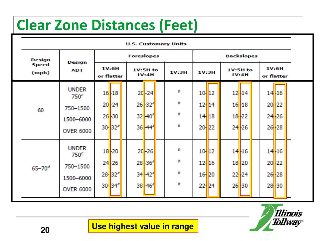
By creating Clear Zones, roadway agencies can increase the likelihood that a roadway departure results in a safe recovery rather than a crash, and mitigate the severity of crashes that do occur.
A10.) Conventional G4 (1S) strong-post guardrail at 29 inches to the top of the rail should have 8-inch blockouts. The size of the blockout is not simply a factor of the height of the guardrail. When the 30- inch maximum height of the G4(1S) guardrail is exceeded an entirely different system is encountered. The generic MGS system with a nominal height of 31” has a blockout that is 12 inches deep, and splices between the posts. The MGS and some of the proprietary 31” systems have the advantage that they will also meet crash test criteria at lower heights, but should be installed at 31” (or slightly higher to accommodate forthcoming overlays).
The minimum 18 inch horizontal clearance to objects behind curbs that is specified in the AASHTO Green Book is a minimum standard offset that allows for normal traffic operations. Because curbs do not deter errant vehicles from leaving the traveled way, the minimum horizontal clearance does not provide a clear zone sufficient to accommodate errant vehicles. The recommended clear zones in the AASHTO Roadside Design Guide (RDG) are based on the design speed of the facility and the slope of the roadside and are not affected by the presence of curbs. It is recognized that providing a clear zone as recommended in the RDG may not be practical in low speed curbed facilities because of right-of-way constraints and other realities of the built environment and a design exception is not required in these cases.
This section presents a brief outline of changes from the 3rd edition, plus provides additional detail on certain significant issues that may affect State design standards. Title 23 USC 109 provides that projects (other than highway projects on the NHS) shall be designed, constructed, operated, and maintained in accordance with State laws, regulations, directives, safety standards, design standards, and construction standards. Over the next several years, more and more tests incorporated “delineator” style vertical elements as this became the in service condition of nearly all curbing systems utilized in this country. Q17.) Do we need to have the vertical devices (road tubes, vertical panels, etc.) in place when crash testing a “curbing” system as a work zone device in Category II. A4.) FHWA does not recommend altering a conventional w-beam rail by drilling new holes to accommodate the MGS. If the rail does not come with slots pre-punched at the 3’ 1 1/2” mark, attempting to drill a new hole may compromise the performance of the rail or constrain its lateral movement.
Attachment No. 1 is a summary of major changes between the 4th edition and earlier editions.Attachment No. 2 is a compilation of questions and answers. Regardless of the type of system being used, a safe runout distance is needed beyond the beginning of the system, either for the situation where the vehicle passes through the system, or where the vehicle just misses the end of the system and continues behind it. Likewise, proper grading providing an essentially flat pad and traversable side slopes to ensure stability of the vehicle is needed, regardless of the type of system. The terminal is only re-directive beyond the point of length of need, which should be specified by the manufacturer.
Regarding the design of new railing standards for both "on and off" NHS routes, Load and Resistance Factor Design (LRFD) Section 13 should apply to all new bridges and rehabilitated bridge projects where railing replacement is required. Further support for this position can be referenced to the FHWA memorandum dated May 30, 1997. Please also be reminded that a new railing detail solely designed to the LRFD geometric and resistance requirements does not necessarily warrant "passing" of a full scale NCHRP 350 crash test at the specified performance level.
AASHTO's Roadside Design Guide presents a synthesis of current information and operating practices related to roadside safety and focuses on safety treatments that can minimize the likelihood of serious injuries when a motorist leaves the roadway. The Office of Safety's July 20, 2007, memorandum on Cable Barrier Considerations dealt with numerous issues of cable barrier design, selection, and placement. Additional guidance on cable barrier selection and placement on sloping terrains and adjacent to median ditches will be provided in conjunction with National Cooperative Highway Research Project 22-25, scheduled for completion in early 2010.

Comments
Post a Comment